2015 CE Code — Part 1 Changes: I
Steve Douglas
Read Part 2 of CE 2015 Code Changes here.
Read Part 3 of CE 2015 Code Changes here.
Read Part 4 of CE 2015 Code Changes here.
Read Part 5 of CE 2015 Code Changes here.
This is the first of several articles published by the International Association of Electrical Inspectors that details significant changes for the 2015 Canadian Electrical Code Part I (CE Code).
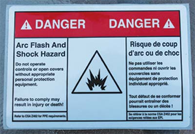
Warning and caution markings
A new rule has been added to Section 2 regarding warning and caution markings. This new rule requires field installed warning and caution markings required by the CE Code to be written in the language(s) mandated by the local authorities having jurisdiction. Examples of filed installed warning and caution markings are the arc flash markings required by Rule 2-306 and the danger high voltage markings required by Rule 36-006. An example of marking NOT required by this new rule to be written in the language(s) mandated by the local authorities having jurisdiction is the panel schedule required by Rule 2-100(3).

Rule 2-126
The flame spread requirements of the National Building Code of Canada have been expanded in the Appendix B note for Rule 2-126 to include FT6 cables intended for air plenums.
Rule 4-004
Rule 4-004 has a new subrule allowing the size of service conductors for single dwellings and feeder conductors supplying single dwelling units of row housing of apartment and similar buildings to be selected in accordance with a new Table 39. The new subrule and table result in conductor sizing similar to those allowed in the 2009 CE Code. This subrule and new table have two limitations. First, the connected distribution equipment must have a conductor termination temperature of not less than 75° C. Second, the 5% allowance in Rule 8-106(1) cannot be used in conjunction with Table 39.
Rain-tight connectors and couplings
The term rain-tight has been replaced with wet location in Section 6 and Section 12. The reasons for this change were to provide clarification as to where the specific connectors and couplings can be used and to align with recent changes to CSA Standard C22.2 No 18.3 Conduit, Tubing, and Cable Fittings.

Rule 10-208
Rule 10-208 has a new Subrule (2) for buildings housing livestock supplied from distribution equipment. This new subrulerequires the buildings housing livestock to be supplied only from a feeder or branch circuit with the non-current-carrying metal parts of the electrical equipment in or on the building or structure bonded to ground by a bonding conductor run with the feeder or branch circuit conductors. The reason for this change is to address stray voltages also known as tingle voltage on farms. The impact on installations may be significant, particularly where the electrical contractor does not install a bond conductor with the feeder to buildings housing livestock, as this subruleno longer allows the feeder neutral to be bonded to ground at the buildings housing livestock.

A sample wet location EMT coupling and connector previously known as rain-tight coupling and connector
Table 16
Table 16 has been divided into two tables, Table 16A and 16B. Table 16A provides the size of bonding conductors based on the size of the largest ungrounded conductor, and Table 16B provides the size of bonding conductors based on the ampacity of the largest ungrounded busbar. The rationale for the change to Table 16 was to provide clarification as to the minimum size of bond conductors required. The previous Table 16 based on the ampacity of the largest ungrounded conductor led to confusion by code users unsure of what allowable ampacity to apply to the bonding table.

Rule 10-906
The word “conductor” has been replaced with “connection” in Subrule (3) of Rule 10-906. The previous wording using the word “conductor” required each bond conductor to be secured directly to the metal box. As an example, where four cables enter a metal box all four bond conductors (the bonding conductor) must be connected directly to the metal box. The bare conductor in each cable is “the bond conductor.” A literal interpretation of Subrule (3) requires the bond conductor to be secured to every metal box by means of a bonding screw as shown in photo 6.

A device box with the bond conductor from each non-metallic sheathed cable terminating directly to the device box bonding screw
Changing the word “conductor” to “connection” recognizes the existing practice of terminating a bond conductor directly to the metal box then connecting all the bond conductors together with a twist-on type connector as shown in photo 7.

A device box with the bond conductor from one non-metallic sheathed cable terminating directly to the device box bonding screw, with the rest of the bond conductors connected to the one conductor that is directly connected to the device box
Rule 12-610
Subrule (1) of Rule 12-610 has been divided into two items. Item (a) still requires an insulating bushing (anti-shorts) or equivalent protection installed between the conductors and the armour of armoured cable. Item (b) is a new requirement for armoured cable provided with an inner jacket (Tech 90); the inner jacket is now required to protrude a minimum of 5 mm beyond the armour (see photo 9). In addition, an Appendix B note has been added to clarify that the paper or plastic wrap around the cable core, directly under the armour of an armoured cable, is not considered the inner jacket (see photo 8).

An insulating bushing (anti-shorts) installed between the conductors and the armour of armoured cable visible from inside an enclosure where the cable is terminated

The inner jacket of a Tech 90 cable protruding beyond the armour
Rule 12-1014
The general raceway fill requirements in Rule 12-1014 have been moved to the 12-900 series of rules for raceways. In addition, all the corresponding individual raceway references to Rule 12-1014 have been updated. The rationale for this change to the existing Rule 12-1014 provides direction for rigid metal and metal flexible conduit without clear direction for other types of conduit or tubing. The change locates the requirements in with the general rule for raceways.
Table 9
Table 9 has been changed dramatically. Table 9 has been expanded into 10 tables. Tables 9A through 9J cover the cross-sectional areas of the following circular raceways:
• Table 9A – CSA C22.2 No 22.2 No. 45 Rigid metal conduit
• Table 9B – CSA C22.2 No 22.2 No. 56 Flexible metal conduit
• Table 9C – CSA C22.2 No 22.2 No. 211.2 Rigid PVC conduit
• Table 9D – CSA C22.2 No 22.2 No. 211.1 Rigid Types EB1 PVC conduit
• Table 9D – CSA C22.2 No 22.2 211.1 No. Rigid Types DB2/ES2 PVC conduit
• Table 9E – CSA C22.2 No 22.2 No. 211.3 Rigid RTRC conduit Type IPS
• Table 9F – CSA C22.2 No 22.2 No. 211.3 Rigid RTRC conduit Type ID
• Table 9G – CSA C22.2 No 22.2 No. 56 Metallic Liquid-tight flexible conduit
• Table 9H – CSA C22.2 No 22.2 No. 227.2 Non-metallic Liquid-tight flexible conduit
• Table 9I – CSA C22.2 No 22.2 No. 83 and C22.2 No 22.2 No. 83.1 Electrical metallic tubing
• Table 9J – CSA C22.2 No 22.2 No. 227.1 Electrical non-metallic tubing
The reason for the additional tables is the internal diameter in the raceway standards listed above is different for individual raceway types.
Table 6
Table 6 has 11 individual tables. The individual tables have separate table numbers from 6A to 6K for easier reference.
As a result of the change to Table 9, the existing Table 6 was inaccurate and needed to be updated. A new table was created based on the smallest size of conduit and tubing available (see figure 1). Figure 1 shows the CSA standard number and the smallest conduit or tubing size. Note: The smallest internal diameters are identified in red.

This table shows the CSA standard number and the smallest conduit or tubing size used to calculate new Tables 6A to 6K

An example of an installation of rigid conduit covered by new Table 9A
The most dramatic change in Table 6 is in the 16 trade size (1/2?). As an example, if #14 AWG 600V T90 nylon conductors installed in a raceway; Table 6 from the 2012 CE Code allows 12 conductors in the raceway, while the 2015 CE Code Table 6K allows only 7 conductors because Table 6K is based on the smallest 17 trade size raceway that is Rigid RTRC ID conduit. As alternative to using a Table 6, the maximum number of conductors that can be installed in a specific raceway can be calculated using the new appropriate Table 9. Using the same example as above with a rigid metal conduit and the new Table 9A the maximum number of conductors is 13.
Read Part 2 of CE 2015 Code Changes here.
Read Part 3 of CE 2015 Code Changes here.
Read Part 4 of CE 2015 Code Changes here.
Read Part 5 of CE 2015 Code Changes here.
Steve Douglas is an IAEI International Past President. He is also the Senior Technical Codes Specialist for QPS Evaluation Services. As the International Association of Electrical Inspectors representative on Part I and Part II of the Canadian Electrical Code, Steve is the vice chair of the CE Code Part I, chair of CE Code Part I Subcommittees for Section 2, and 12, and a member on Sections 40, 64, 68, 76 and Appendix D. In addition, Steve is Chair of the CSA Standards C22.2 No. 273 Cablebus, C22.6 No. 1, Electrical Inspection Code for Existing Residential Occupancies committee, Chair of the SPE-1000 Working Group, and a member on committees for the Objective Based Industrial Electrical Code, Safety Management Systems, Solar Photovoltaic Modules, Photovoltaic Cable, Fuel Cells, Wind Turbines, Distribution transformers, Outlet Boxes, and Wiring Fittings Hardware and Positioning Devices.


![Guide to the Canadian Electrical Code, Part 1[i], 26th Edition – A Road Map: Section 10 – Grounding and Bonding](https://electricalindustry.ca/wp-content/uploads/2022/11/Guide-CE-Code-2.png)