2015 CE Code — Part 1 Changes: II
Steve Douglas
Read Part 1 of CE 2015 Code Changes here.
Read Part 3 of CE 2015 Code Changes here.
Read Part 4 of CE 2015 Code Changes here.
Read Part 5 of CE 2015 Code Changes here.
This is the second of three articles detailing significant changes for the 2015 Canadian Electrical Code Part I (CE Code). The rules in this article are limited to changes already adopted by CE Code Technical Committee and not subject to further changes.
Table 10
Table 10 now has four tables with the addition of 10C and 10D. Table 10C has been added for the dimensions of solid conductors for calculating conduit and tubing fill, and Table 10D is for the dimensions of DLO cables for calculating conduit and tubing fill. In addition to the new tables, stranded conductor classes have been added to Tables 10A and 10B. The main reason for the Table 10 changes was to recognize that the data in Tables 10A and 10B are for stranded conductors and to provide the required conductor and cable dimensions for solid conductors and DLO cable.
Photo 1. DLO cable covered now by CE Code Table 10D
Rule 12-1402
The permitted use of electrical metallic tubing has been expanded to include wet locations. The rationale for this change was to recognize the change for the designation of connectors and coupling from rain-tight to wet location type in CSA Standard C22.2 No 18.3 Conduit, Tubing, and Cable Fittings, and the change in the corrosion protection requirements of electrical metallic tubing in CSA Standard C22.2 No 83.1 Electrical Metallic Tubing — Steel.

Photo 2. An example of EMT installed outdoor with wet location connectors and couplings.
Rule 12-1412
The bonding requirements for electrical metallic tubing has been moved to a new Rule 12-1402, including a new requirement for a bond conductor in all electrical metallic tubing installed in a wet location.
Rule 26-700
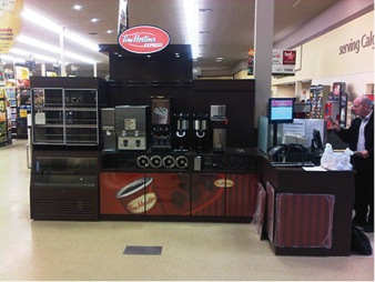
New Subrule (13) has been added to Rule 26-700; receptacles located 2 m from the floor or finished grade or installed for dedicated stationary appliances shall not be required to be tamper resistant.

Photo 3. An example of a stationary appliance
Rule 26-956
In Rule 26-956 regarding the installation of submersible pumps, the words “lakes, rivers, and streams” have been replaced with “bodies of water”. The intent of this change was to add other bodies of water such as seas and oceans, to ensure the requirements of this rule apply to all bodies of water.
Rule 28-900
Rule 28-900 regarding the disconnecting means required for generators has been rewritten. This new requirement for generators will require a separate disconnecting means for each generator and for each circuit supplying all protective devices and control apparatus required for operation of the generator. The disconnecting means can be an integral part of the generator or installed as part of the installation. The rationale for this new wording is to provide clearer requirements, consistency of installations, and to remove product standard requirements from the CE Code.
Rule 34-110
Subrule (2) of Rule 34-110 has been revised to allow subassemblies of sign or outline lighting systems not to be bonded provided the subassemblies are supplied by a remote Class 2 power supply with an output not exceeding 30V. The rationale for this change was to provide consistency with existing bonding requirements in Sections 10 and 16.
Photo 4. An example of a class 2 sign that does not require bonding.
Section 50
Section 50 Solar photovoltaic systems have been amalgamated with Section 64 Renewable energy systems. The definition of Panel has been deleted, and the definitions of Array and Module have been revised.
The definition of module has been changed to “Photovoltaic module — the smallest a complete and environmentally protected assembly of interconnected solar cells.” The definition of array is “a mechanically integrated assembly of photovoltaic modules with the reference to panel removed.” The rationale for these changes was to have consistent definitions with the new CSA Standard C22.2 No 61730-1 Photovoltaic module safety qualification — Part 1: Requirements for construction.

Photo 5. A photovoltaic array with 10 photovoltaic modules
Rule 50-006
Two new subrules have been added to the existing Rule 50-006. New Subrule (4) will limit the maximum DC voltage from photovoltaic source and output circuit voltage in or on dwelling units to 600V. This subrule will also require access to energized parts over 150V to qualified persons only, and circuits inside the building that are over 30 volts to be installed in metallic raceways, metal enclosures, or cables with a metal armour or metal sheath. The rationale for this subrule was to address installation in dwelling units between 30 and 600V DC and to harmonize with exiting requirements in Section 64.
New Subrule (5) addresses non-dwelling unit installations with a maximum DC circuit voltage between 750 and 1000V. This new subrule will exempt DC photovoltaic installations between 750 and 1000V from meeting the visible isolation and interlocking requirements of Rules 36-204, 36-208, and 36-214 for high voltage installations. This subrule was added to address the increasing number of photovoltaic farms with DC voltages up to 1000V.

Photo 6. A 1000V DC breaker nameplate. Note: this breaker is not of the drawout type and does not provide visible isolation
50-018
Two new subrules have been added to Rule 50-018. The first addition requires photovoltaic module interconnecting cables be supported at intervals of not more than 1 m and within 300 mm of every box or connector, and that the cables be protected against mechanical damage during and after the installation. An Appendix B note has also been added to clarify that the intent of subrule is to prevent damage to solar photovoltaic cable from rubbing on surfaces such as roofing and array structures. The second new subrule will require photovoltaic source circuits installed on or above a building to be protected against damage from rodents unless DC arc-fault protection is located at the module. An Appendix B note has also been added indicating that material such as expanded metal, solid metal, and screening can be used to enclose photovoltaic source circuit conductors as protection against damage from rodents. The rationale for this subrule was to address concerns raised during the development of the recently published CSA SPE-900 Solar photovoltaic rooftop-installation best practices guideline.

Photos 7 and 8 are photovoltaic source circuit cables damaged by rodents
New rule for conductor marking or colour coding
A new rule will require DC photovoltaic circuits installed between the modules and the power conditioning unit to be identified as red for positive and black for negative, or black conductors manufactured with permanent surface printing indicating the polarity on the conductor. This subrule will not allow field marking or labelling of single conductors; the cable must be supplied with permanent identification. Field colour-coding for conductors of multi-conductor cables will be permitted provided the colour-coding for conductors is at every point where the separate conductors are accessible. An Appendix B note has been added to indicate that CSA Standard C22.2 No 271 Photovoltaic Cables allows the positive or negative identification on RPV or RPVU conductor cables to be “+/–”, “pos/neg”, or “positive/negative”. The rationale for this new rule was a direct result of photovoltaic installation fires caused by unidentified and misidentified conductors connected reverse polarity.

Photo 9. A typical midway where ground-fault circuit interrupters of the Class A type is are required for all 15- and 20-amp 125V receptacles intended to supply loads in outdoor or damp locations.
Rule 66-404
This new rule will require ground-fault circuit interrupters of the Class A type for all 15- and 20-amp 125 V receptacles intended to supply loads in outdoor or damp locations in midways, carnivals, fairs and festivals. The proposal for this rule change was an IAEI-endorsed proposal. The majority of these rides and shows are set up in temporary locations, and have cords running through mud and water and strung around the aluminium barricades protecting and enclosing the rides. The condition of these cords is constantly in question and unless caught they are often not of the hard usage type as required by the code. By requiring the supply of power to be ground-fault circuit interrupter protected, we are reducing the risk of a possible fault from resulting in a fatality.

Photo 10. 125 V receptacles on a wharf
Rule 78-052 and 78-102
Subrule (4) of Rule 78-052 and Subrule (3) of Rule 78-102 covering receptacles installed outdoors or on fixed or floating piers, docks, or wharves has been revised, deleting the exception for receptacles supplying shore power to boats. All 125-V, 15- and 20-amp receptacles installed on fixed or floating piers, docks, or wharves will now be required to be protected by a ground-fault circuit interrupter of the Class A type. The rationale for these changes was to address a shock hazard when wiring systems supplying shore power become damaged inadvertently.

Photo 11. A 208 V motor now recognized in Table 44.
Photo 12. A sample of a motor nameplate for a 208V motor.
Table 44 Three-phase AC motors
Full load current values have been added for induction type, squirrel cage and wound rotor, 208V motors. The easier to use addition of this new column for 208V motors removes the need to calculate any value, which makes the table.
Read Part 1 of CE 2015 Code Changes here.
Read Part 3 of CE 2015 Code Changes here.
Read Part 4 of CE 2015 Code Changes here.
Read Part 5 of CE 2015 Code Changes here.
Steve Douglas is an IAEI International Past President. He is also the Senior Technical Codes Specialist for QPS Evaluation Services. As the International Association of Electrical Inspectors representative on Part I and Part II of the Canadian Electrical Code, Steve is the vice chair of the CE Code Part I, chair of CE Code Part I Subcommittees for Section 2, and 12, and a member on Sections 40, 64, 68, 76 and Appendix D. In addition, Steve is Chair of the CSA Standards C22.2 No. 273 Cablebus, C22.6 No. 1, Electrical Inspection Code for Existing Residential Occupancies committee, Chair of the SPE-1000 Working Group, and a member on committees for the Objective Based Industrial Electrical Code, Safety Management Systems, Solar Photovoltaic Modules, Photovoltaic Cable, Fuel Cells, Wind Turbines, Distribution transformers, Outlet Boxes, and Wiring Fittings Hardware and Positioning Devices.


![Guide to the Canadian Electrical Code, Part 1[i], 26th Edition – A Road Map: Section 10 – Grounding and Bonding](https://electricalindustry.ca/wp-content/uploads/2022/11/Guide-CE-Code-2.png)