Conductor Selection in Practice: A Code-Based Approach to Cable Sizing
July 6, 2026
By Sophia Shereni, P.Eng
Proper cable sizing is a critical part of electrical system design, it directly affects safety, reliability, and equipment performance. At first pass, it’s easy to assume that matching a conductor’s ampacity to the circuit’s full load current is sufficient. In practice, it rarely is. Cable sizing under the Canadian Electrical Code is not a single lookup; it’s a sequence of constraints, each one capable of overriding the last.
A conductor that satisfies ampacity may fail after ambient correction. One that clears derating may still be disqualified by its termination temperature rating. This article walks through each criterion in order using a worked example, a 28 hp, 3-phase, 600 V motor circuit to show how the conductor selection evolves from first pass to final selection.
Ambient Temperature
The ampacity tables in CSA C22.1 are based on a standard ambient temperature of 30 °C. In practice, many installations exceed this reference condition.
Electrical rooms, rooftops, and areas near heat-generating equipment are common examples. When the actual ambient temperature is higher than 30 °C, the allowable current-carrying capacity of the conductor must be reduced.
This adjustment to account for ambient temperature is done by applying a temperature correction factor from CSA C22.1, Table 5A.
Termination Temperature Limits
Electrical cables are manufactured with defined insulation temperature ratings. However, the equipment they connect to may be rated for a lower temperature.
Circuit breakers, panelboards, generators, and motor terminals all have termination ratings. To avoid overheating at connection points, conductor ampacity must be based on the termination temperature rating, not solely on the insulation rating. Where the two differ, the lower rating governs.
This is an important practical point. Although 90 °C cables are commonly installed, they cannot always be loaded to their full 90 °C ampacity. In many applications, a larger conductor is required to meet the ampacity requirement while staying within the termination limit.
Cable Bundling
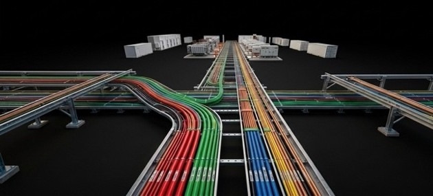
When multiple conductors are installed in the same conduit or cable tray, heat dissipation is reduced. A single conductor can transfer heat to the surrounding air relatively efficiently. When conductors are grouped together, the overall heat output raises the local ambient temperature.
The result is a higher conductor operating temperature and a lower allowable current-carrying capacity for each conductor in the group.
Because of this, a derating factor must be applied when more than three current-carrying conductors are grouped together (CSA C22.1, Table 5C). As more conductors are added, the derating becomes greater, meaning a conductor that is adequate when installed alone may no longer be sufficient when bundled.
Voltage Drop
Electrical equipment is designed to operate at a specific voltage, and CSA C22.1, Rule 8-102 typically limits voltage drop to 3% for branch circuits and 5% overall from service entrance to point of use.
As current flows through a conductor, a voltage drop occurs due to its impedance. This loss increases with circuit length – a factor that ampacity calculations don’t account for. A conductor can be perfectly sized for current-carrying capacity and still deliver insufficient voltage at the load end.
This is especially important for motors. Low voltage reduces starting torque, increases current draw, and can prevent the motor from reaching its rated speed. At this point, circuit length becomes a key design factor.
For longer runs, voltage drop can become the governing factor, requiring a larger conductor even where all ampacity checks have already been satisfied.
Worked Cable Sizing Example
| PARAMETER | VALUE |
| LOAD | 28 hp, 3-phase motor |
| SUPPLY VOLTAGE | 600V, 3-phase |
| CABLE TYPE | Copper, 90 °C rated |
| INSTALLATION METHOD | Cable Tray |
| AMBIENT TEMPERATURE | 40 °C |
| NUMBER OF CONDUCTORS IN TRAY | Maximum |
| NUMBER OF CONDUCTORS IN CABLE | 2+ |
| CABLE LENGTH | 30 m |
| FULL LOAD CURRENT (FLA) | 28 A |
| AMPACITY | 35 A |
CSA C22.1 Rule 28-106 Minimum Ampacity: Motor branch circuit conductors must be sized for a minimum of 125% of FLA.
Design Ampacity = 1.25 × 28 A = 35 A (this value governs all subsequent steps)
Step 1 – Base Ampacity (CSA C22.1 Table 2)
From CSA C22.1, Table 2, a #10 AWG copper conductor has a base ampacity of 40 A at 90 °C. This exceeds the FLA of 35 A and is selected as the starting candidate.
Step 2 – Ambient Temperature Correction (CSA C22.1 Table 5A)
Ampacity tables assume a 30 °C ambient temperature. Since the actual ambient is 40 °C, a correction factor must be applied. From CSA C22.1, Table 5A, for 90 °C insulation at 40 °C ambient, correction factor is 0.91.
#10 AWG:
| Calculation Result | |
| Base ampacity (#10 AWG, 90 °C, Table 2) | 40 A |
| Ambient correction (×0.91, Table 5A) | 40 × 0.91 = 36.4 A ✓ |
36.4 A > 35 A. #10 AWG passes ambient correction. Proceed to bundling check
Step 3 – Bundling Derating (CSA C22.1 Table 5C)
Mutual heating in cable tray reduces each conductor’s ability to dissipate heat.
Design Note: Raceway often start out only partially filled, but as projects grow and routing changes, they usually end up fully loaded. Designing for the worst-case derating (43+ conductors) from the beginning helps avoid having to resize conductors later.
#10 AWG
| Calculation Result | |
| Base ampacity (#10 AWG, 90 °C, Table 2) | 40 A |
| Ambient correction (×0.91, Table 5A) | 40 × 0.91 = 36.4 A ✓ |
| Bundling derating (×0.5, Table 5C) | 36.4 × 0.5 = 18.2 A ✗ |
18.2 A < 35 A. #10 AWG fails bundling derating. Step up to #8 AWG.
#8 AWG
| Calculation Result | |
| Base ampacity (#8 AWG, 90 °C, Table 2) | 55 A |
| Ambient correction (×0.91, Table 5A) | 55 × 0.91 = 50.1 A ✓ |
| Bundling derating (×0.5, Table 5C) | 50.1 × 0.5 = 25.1 A ✗ |
25.1 A < 35 A. #8 AWG fails bundling derating. Step up to #6 AWG.
#6 AWG
| Calculation Result | |
| Base ampacity (#6 AWG, 90 °C, Table 2) | 75 A |
| Ambient correction (×0.91, Table 5A) | 75 × 0.91 = 68.3 A ✓ |
| Bundling derating (×0.5, Table 5C) | 68.3 × 0.5 = 34.1 A ✗ |
34.1 A < 35 A. #6 AWG fails bundling derating. Step up to #4 AWG.
#4 AWG
| Calculation Result | |
| Base ampacity (#4 AWG, 90 °C, Table 2) | 95 A |
| Ambient correction (×0.91, Table 5A) | 95 × 0.91 = 86.5 A ✓ |
| Bundling derating (×0.5, Table 5C) | 86.5 × 0.5 = 43.2 A ✓ |
43.2 A > 35 A. #4 AWG satisfies ampacity after bundling derating
Step 4 – Termination Temperature Limitation (CSA C22.1 Rule 4-006)
Although the cable is rated 90 °C, the connection terminals are rated 75 °C. Per CSA C22.1 Rule 4-006, the lower temperature governs. Ampacity must be re-evaluated using the 75 °C column of CSA C22.1 Table 2. The ambient correction factor at 40 °C for 75 °C insulation is 0.88 (Table 5A).
#4 AWG at 75 °C:
| Calculation Result | |
| Base ampacity (#4 AWG, 75 °C, Table 2) | 85 A |
| Ambient correction (×0.88, Table 5A) | 85 × 0.88 = 74.8 A ✓ |
| Bundling derating (×0.5, Table 5C) | 74.8 × 0.5 = 37.4 A ✓ |
37.4 A > 35 A, #4 AWG satisfies ampacity under all conditions including the 75 °C termination constraint.
Step 5 – Voltage Drop Verification (CEC Rule 8-102)
CSA C22.1, Rule 8-102 limits voltage drop to 3% for branch circuits. With a 30 m run, voltage drop is evaluated to confirm it is not a governing sizing factor.
#4 AWG at 75 °C:
| Calculation Result | |
| Voltage Drop AC Cosφ=power factor=0.8, R=1.01 Ω/km, X=0.109 Ω/km | = √3 × I × L × (R cosφ + X sinφ) = √3 × 28 × (30/100) × [(1.01 × 0.8) + (0.109 × 0.6)] = 12.7 V |
| %VD | (12.7 / 600) × 100 = 2.12% ✓ |
Final Summary
| Sizing Check | Requirement | #10 AWG | #8 AWG | #6 AWG | #4 AWG |
| Base ampacity (90 °C, Table 2) | > 35 A | 40 A ✓ | 55 A ✓ | 75 A ✓ | 95 A ✓ |
| After ambient correction (×0.91) | > 35 A | 36.4 A ✓ | 50.1 A ✓ | 68.3 A ✓ | 86.5 A ✓ |
| After bundling derating (×0.5) | > 35 A | 18.2 A ✗ | 25.1 A ✗ | 34.1 A ✗ | 43.2 A ✓ |
| After termination limit 75 °C (×0.88, ×0.5) | > 35 A | – | – | – | 37.4 A ✓ |
| Voltage Drop | < 3% | – | – | – | 2.12 % ✓ |
Cable sizing is not a one-step process. In this example, a circuit that first looked suitable for #10 AWG ended up requiring #4 AWG once real installation conditions were considered. Each adjustment may seem small, but together they add up. Designing based on ideal conditions can easily lead to undersized conductors in practice.
![Guide to the Canadian Electrical Code, Part 1[i], 26th Edition– A Road Map: Section 74 — Airport installations](https://electricalindustry.ca/wp-content/uploads/2026/05/EIN-Stock-Guide-Code-Canada-Map-1200-768x403.png)




![Guide to the Canadian Electrical Code, Part 1[i], 26th Edition– A Road Map: Section 74 — Airport installations](https://electricalindustry.ca/wp-content/uploads/2026/05/EIN-Stock-Guide-Code-Canada-Map-1200.png)