DC Resistance Unbalance Testing: Easy, Low-Cost Insurance for Your PoE Systems, Part 2

August 15, 2016
In the previous issue of Electrical Industry News Week, we looked at what causes DC resistance unbalance. In this issue: testing for DC resistance unbalance within a pair and between pairs.
IEEE Std 802.3-2012 specifies a maximum DC resistance unbalance of 3% between conductors, meaning that the difference in DC resistance between two conductors is no more than 3% of the total DC loop resistance of a pair. However, both TIA and IECs standards do not require DC resistance unbalance testing within a pair or DC resistance unbalance testing between pairs as a field measurement. The lack of field test requirement has been in part due to no field tester that was capable of testing for DC resistance unbalance, so it was left as a laboratory measurement only. That is no longer the case with the DSX-5000 CableAnalyzer. Furthermore, the proposed IEEE 802.3bt standard requires the DC resistance unbalance between two pairs to be no more than the greater of 7% or 50m Ω.
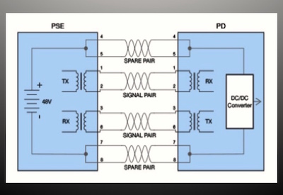
DC resistance unbalance testing verifies that the conductors in a pair have equal resistance and will therefore enable the common-mode current needed to effectively support PoE and avoid distortion of the data signals transmitting on the same pair. Unlike other field testers that only test DC loop resistance, the DSX-5000 measures DC loop resistance, DC resistance unbalance within a pair and DC resistance unbalance between pairs.
As shown in the figure below, the DSX-5000 measures DC loop resistance as a sum of the resistance of two conductors in a pair, while DC resistance unbalance is a measure of the difference in resistance between the two conductors. DC resistance unbalance between pairs is shown for pairs 1,2-4,5, being the absolute difference in the parallel resistances of the two pairs.
While not required in field testing, the DSX-5000 CableAnalyzer can be configured to include DC Resistance Unbalance test limits for either Channel or Permanent Link Measurements; as shown in the table below.
If you are making a permanent link or channel measurement, the measurement is made by the DSX-5000 with a PASS/FAIL applied for the test limit selected, as shown in the figure below. This is useful information if you observe PoE issues and want to rule out the cabling as a potential cause and gives you confidence that newly installed cabling will not only transmit data but can also support PoE.
With field testing standards being a minimum set of test requirements, consideration should be given to including DC resistance unbalance testing as an extended field testing requirement, to help deal with issues surrounding CCA cable and to provide greater assurance for meeting IEEE-mandated PoE requirements.
Testing for DC resistance unbalance within a pair and DC resistance unbalance between pairs will become of even greater concern as more enterprise entities deploy multiple gigabit Ethernet technologies and more PoE devices that utilize methods of delivering power simultaneously with data. As the deployment of PoE Plus continues to grow, especially with the introduction of 802.11ac WAPs that require it, DC resistance unbalance will become an even greater concern as more current flowing through a conductor makes PoE even more susceptible to DC resistance and resistance unbalance. On the horizon is PoE Plus Plus, offering even higher power for devices that require up to 60 Watts.
Don’t let your PoE systems hang in the balance. Requiring DC resistance unbalance testing via the DSX-5000 is an easy, low-cost insurance for today’s and tomorrow’s PoE systems.
Increase termination consistency with the right termination tool
Using the correct termination tool can help increase termination consistency and avoid DC resistance unbalance in PoE systems. There are three types of punchdown tools for terminating telecommunications cables: manual, impact and multi-wire. Manual punchdown tools require the bulk of the force to come from human power, which has the potential for higher inconsistency across two conductors of a pair. It’s very difficult to use the exact amount of force for each conductor every time, especially once hand fatigue sets in.
Impact tools that require less force on the part of the installer are a better option, but these tools can still result in termination inconsistency from conductor to conductor. The best option for ensuring termination consistency are multi-wire tools such as JackRapid that terminate all pairs with one squeeze, providing an equivalent amount of force on all conductors. Multi-wire tools also ease hand fatigue and significantly cut installation time by terminating jacks up to eight time faster compared to using single-wire termination tools. The combination of faster, more reliable and consistent terminations reduces rework and cost by as much as 80%.
DC loop resistance vs. dc resistance unbalance
There is often some confusion over the difference between DC loop resistance and DC resistance unbalance. The ability to deliver a certain amount of power is dependent on the total DC loop resistance of a specific length of cable. DC loop resistance is calculated as the sum of the DC resistance of two conductors in a pair. According to IEEE standards, the channel DC loop resistance of a pair shall be 25 Ω or less while permanent link DC loop resistance shall be 21 Ω or less.
Read Part I : DC Resistance Unbalance Testing: Easy, Low-Cost Insurance for Your PoE Systems, Part 1
This article was originally published online by Fluke: www.flukenetworks.com/content/white-paper-dc-resistance-unbalance-testing-easy-low-cost-insurance-your-poe-systems.


![Guide to the Canadian Electrical Code, Part 1[i], 26th Edition– A Road Map: Section 34](https://electricalindustry.ca/wp-content/uploads/2022/11/Guide-CE-Code-2.png)


