Residential EV Charging: From the First Electric Cars to Intelligent and Wireless Energy Systems
November 20, 2026
By Arnaldo S. Attallah, P.Eng. (Retired), M.Sc. (INRS Énergie)
Historical development, present technologies, and the near future of residential electric vehicle charging
1. Introduction: More Than a Century of Electric Vehicle Charging
Electric vehicle (EV) charging is not a recent invention. During the late nineteenth century, electric automobiles emerged alongside gasoline-powered and steam-powered vehicles. By the beginning of the twentieth century, electric cars had become a practical transportation option, particularly in urban areas. Their batteries required regular recharging, but the electrical equipment used at that time was fundamentally different from today’s standardized charging systems.
The widespread adoption of gasoline-powered automobiles, improvements in internal combustion engines, and the availability of inexpensive petroleum contributed to the decline of electric passenger vehicles during the first half of the twentieth century. Interest in electric propulsion gradually returned, particularly during the energy crises of the 1970s and the development of new environmental regulations.
The modern electric vehicle revival accelerated with the General Motors EV1 in 1996, the Tesla Roadster in 2008, and the Nissan LEAF and Chevrolet Volt in 2010. These developments created a growing requirement for safe, practical, and standardized charging equipment suitable for residential use.
The historical evolution of electric vehicles is documented by the United States Department of Energy.
2. Residential Electrical Supplies: 50 Hz and 60 Hz
Residential electric vehicle charging must operate within the characteristics of the electrical network supplying the installation.
Two nominal alternating-current (AC) frequencies are widely used worldwide:
- 60 Hz (60 cycles per second) in Canada, the United States, and several other countries.
- 50 Hz (50 cycles per second) throughout Europe and in many other countries, including China, India, and Australia.
- Japan is an important exception, with different regions operating at either 50 Hz or 60 Hz.
- North American residences commonly use 120/240 V split-phase electrical services.
- In Europe, common nominal supplies include 230 V single-phase and 230/400 V three-phase systems.
Charging equipment must therefore be designed and rated for the voltage, frequency, phase arrangement, grounding system, and electrical regulations applicable to its intended market. The international IEC 62196-2:2025 standard addresses standardized AC charging accessories operating at nominal frequencies from 50 Hz to 60 Hz.
These differences are particularly important when designing charging equipment for international markets.
3. From Conventional Charging to Smart Charging
In North America, residential AC charging is generally divided into two categories.
- Level 1 charging normally uses a nominal 120 V electrical supply.
- Level 2 charging commonly uses 240 V in residential installations, while 208 V is also used in suitable electrical supply configurations.
For example, a Level 2 charging system operating at 240 V and 40 A has an apparent input power of:
- 240 V × 40 A = 9,600 VA = 9.6 kVA.
If the power factor is close to unity, its active electrical input power is approximately 9.6 kW. This represents a substantial additional household electrical load.
Because EV charging is a continuous load, the supply circuit must be sized above the charger’s maximum current. In Canada, Rules 86-300 to 86-306 of the Canadian Electrical Code (numbering as in the 2021 edition) govern EVSE branch circuits, and Rule 86-302 treats the EVSE load as a continuous load under Rule 8-104. Under the U.S. National Electrical Code, the overcurrent protection must be rated at no less than 125% of the EVSE current rating, so a 40 A charger requires at least a 50 A circuit (NFPA 70, National Electrical Code (NEC), Article 625 — Electric Vehicle Power Transfer System. 2023 edition).
In residences with limited available service capacity, installing a dedicated EV charging circuit can require careful load calculations and potentially costly electrical modifications.
One possible solution is to upgrade the electrical service. Another is to manage charging demand intelligently.
The Canadian Electrical Code explicitly recognizes this approach: Rule 8-500 sets the conditions under which an electric vehicle energy management system (EVEMS) may monitor loads and automatically control EVSE loads, and Rules 8-106(10) and 8-106(11) allow the EVSE demand load to be limited to the maximum load allowed by the EVEMS, or excluded from the calculated load where the EVEMS monitors the service and feeders. The U.S. National Electrical Code contains a comparable provision for energy management systems in section 625.42.
Energy management systems can monitor household electrical consumption and adjust the charging-current limit according to available capacity. Simple load-management systems may interrupt charging when a predetermined threshold is reached. More advanced systems can progressively reduce or restore the permissible charging current as household demand changes. This represents an important transition from simple electrical power delivery toward coordinated electrical energy management.
The general requirements for conductive EV charging equipment are addressed by IEC 61851-1:2017 and its 2023 corrigendum. A fourth edition, retitled “Conductive power and energy transfer systems for electric vehicles – Part 1: General system and specific Mode 3 EV charging station requirements,” reached the final-draft stage in August 2026 and will supersede the 2017 edition when published.
4. Charging Connectors: Standardization Without Worldwide Uniformity
The physical connection between an electric vehicle and its charging equipment has evolved through several regional standards.
- In North America, SAE J1772 Type 1 has been widely used for AC charging.
- SAE J3400, based on the Tesla-origin North American Charging Standard (NACS), provides another standardized interface capable of supporting single-phase AC and DC charging.
- The SAE J3400 connector uses the same principal power contacts for both charging modes, subject to the appropriate electrical operating conditions.
- Both J1772 and J3400 can support conventional AC charging control through Control Pilot signaling.
- In Europe, the IEC Type 2 connector is widely used for AC charging, including single-phase and three-phase applications.
- The Combined Charging System (CCS) extends compatible vehicle inlets with additional contacts for DC charging.
- CCS1 is associated with the North American Type 1 interface, while CCS2 is associated with the European Type 2 interface.
- China uses its own GB/T charging-connector standards (GB/T 20234.1-2023 and GB/T 20234.3-2023 — Connection Devices for Conductive Charging of Electric Vehicles — Part 1: General Requirements; Part 3: DC Charging Interface).
- Japan uses the CHAdeMO interface for DC charging.
- Consequently, no single physical charging connector has been universally adopted by every electric vehicle manufacturer worldwide.
- Manufacturers of residential EVSE equipment must therefore consider the connector requirements of their intended markets.
- Relevant specifications include SAE J1772, SAE J3400, IEC 62196-2, IEC 62196-3, and GB/T 20234.
5. Adaptive Charging and Local Energy Management
One of the most promising developments in residential charging is the integration of local energy management.
A properly engineered energy management system (EMS) can monitor household electrical demand and determine the charging capacity available within the installation’s permitted operating limits. Current sensors and local electronic controllers can provide the information required to adjust charging demand.
In conventional AC charging, the permissible charging current can be communicated to the vehicle through the Control Pilot pulse-width modulation (PWM) signal. The PWM duty cycle indicates the maximum current that the EVSE permits the vehicle to draw. The vehicle’s onboard charger is responsible for respecting that limit. This is an important technical distinction: the EVSE communicates an allowable current rather than directly forcing the vehicle to draw a particular current.
When household electrical demand increases, the controller may reduce the advertised charging-current limit. When household demand decreases, the controller may restore available charging capacity. If sufficient capacity is no longer available to maintain the minimum permitted charging current of 6 A, charging may need to be suspended.
This approach can improve the utilization of existing electrical infrastructure without assuming that every residence requires a service upgrade.
However, any such system must satisfy applicable electrical-code requirements, equipment ratings, protective-device requirements, and relevant certification conditions. Essential load-management and safety functions can be implemented locally, without relying on continuous Internet connectivity. Cloud services may provide monitoring, scheduling, and other conveniences, but they need not be part of the essential local control loop.
- International Electrotechnical Commission. IEC 61851-1:2017 — Electric Vehicle Conductive Charging System — Part 1: General Requirements (with Corrigendum 1:2023).
- SAE International. SAE J1772:2024 — SAE Electric Vehicle and Plug-in Hybrid Electric Vehicle Conductive Charge Coupler
6. ISO 15118-20: Digital and Bidirectional Communication
An important development in EV charging technology is the introduction of advanced digital and bidirectional communication.
ISO 15118-20:2022 specifies second-generation network-layer and application-layer communication requirements between compatible electric vehicles and electric vehicle supply equipment.
It defines structured digital messages and communication sequences exchanged between the Electric Vehicle Communication Controller (EVCC) and the Supply Equipment Communication Controller (SECC).
This enables two-way digital information exchange for charging coordination and advanced energy-transfer services.
Conventional conductive high-level communication can use power-line communication (PLC) technology, specified in ISO 15118-3.
ISO 15118-20 also defines wireless (WLAN) communication, usable with both conductive and wireless charging, with its physical and data-link layers specified in ISO 15118-8; it also describes the communication sequences for wireless power transfer.
Unlike conventional Control Pilot PWM signaling, which primarily communicates basic charging states and permissible AC charging current, ISO 15118-20 provides a higher-level digital communication framework.
The distinction between communication and electrical power transfer is fundamental.
Bidirectional digital communication means that information can be exchanged in both directions.
Bidirectional power transfer means that electrical energy can flow in either direction.
These are separate capabilities. A system may support bidirectional digital communication without supporting reverse electrical energy flow. Actual bidirectional power transfer requires compatible vehicles, power-conversion equipment, protective systems, and appropriate electrical and utility arrangements.
ISO 15118-20 defines communication procedures supporting bidirectional power transfer, but it does not itself guarantee that a particular vehicle or EVSE can export electrical energy. It also does not replace the physical connector standards or applicable electrical safety requirements. Conventional AC charging-current management through Control Pilot PWM does not inherently require ISO 15118-20. The two approaches are technically distinct and may coexist in compatible systems.
7. The Next Frontier: Wireless and Inductive Charging
Wireless power transfer (WPT), commonly called inductive charging, represents another important development in residential EV charging.
Instead of using a conductive cable and connector between the charging equipment and the vehicle, electrical energy is transferred through magnetic coupling.
A typical stationary wireless charging system includes:
- A ground-mounted power-transmitting assembly.
- Power electronics generating an alternating magnetic field.
- A receiving assembly installed on the vehicle.
- Vehicle-side power-conversion and battery-charging electronics.
- Communication, positioning, and safety-control functions.
The transmitter and receiver operate as a magnetically coupled system, generally using resonant inductive power-transfer principles.
Unlike the 50 Hz or 60 Hz frequency of the electrical supply network, standardized automotive inductive charging operates at a substantially higher frequency, commonly near 85 kHz.
Standardization of wireless charging
SAE J2954:2024 establishes requirements for stationary wireless power transfer for light-duty plug-in electric vehicles.
It addresses interoperability, electromagnetic compatibility, electromagnetic fields, minimum performance, safety, and testing.
The standard defines three charging power classes up to 11 kVA. Its 2024 edition covers stationary, unidirectional wireless power transfer from the electrical supply toward the vehicle. The 2024 edition also covers only surface-mounted ground assemblies; flush-mounted installations are planned for a later revision.
Higher-power and bidirectional applications are subjects of further standardization work.
The international IEC 61980 series also addresses wireless power transfer for electric vehicles.
IEC 61980-1:2020 establishes general requirements, including electrical safety, communication, efficiency, alignment, and electromagnetic compatibility.
IEC PAS 61980-4:2025 addresses interoperability and safety requirements for high-power stationary wireless power transfer.
Sources: SAE J2954:2024 and IEC 61980 publications.
An industrial example: Porsche Wireless Charging
Porsche has announced a wireless charging system of up to 11 kW for the Cayenne Electric.
The system incorporates a ground-mounted charging plate and compatible vehicle-mounted equipment. According to Porsche, the technology can achieve an efficiency of up to 90%. This figure is a manufacturer-reported performance claim and should not be interpreted as a universal efficiency value for all wireless charging systems.
The system also incorporates positioning and safety functions, including foreign-object detection. Porsche is launching the system in Europe in 2026, with other markets to follow; no North American date has been announced. This development demonstrates that residential inductive charging is progressing beyond laboratory experimentation toward commercial automotive applications.
Source: Porsche Newsroom.
Advantages and limitations
Wireless charging may offer several practical advantages.
It eliminates the need to handle a charging cable during normal operation and may be particularly convenient for residential garages, accessible parking spaces, and automated parking systems.
However, several technical and economic considerations remain. These include the cost of the transmitting and receiving equipment, installation requirements, positioning accuracy, conversion losses, electromagnetic compatibility, thermal management, and vehicle interoperability.
Wireless charging also requires suitable safety provisions to detect abnormal conditions, including foreign metallic objects near the power-transfer region. Most importantly, wireless charging does not eliminate the electrical capacity limitations of the residence. The electrical energy must still be supplied by the building’s electrical infrastructure. Therefore, wireless charging can also benefit from intelligent local energy management.
A compatible wireless charging controller could, in principle, coordinate its electrical input demand with available household capacity. However, this would require an appropriate control interface with the wireless power-transfer equipment.
The conventional SAE J1772 Control Pilot PWM interface should not automatically be assumed to provide that function.
8. Beyond the Garage: Dynamic Wireless Charging
Researchers and standards organizations are also examining dynamic wireless power transfer (DWPT).
In this approach, transmitting equipment is integrated into roadway infrastructure so that compatible vehicles may receive electrical energy while moving.
The concept could eventually reduce dependence on stationary charging for certain transportation applications.
However, dynamic wireless charging presents additional challenges involving infrastructure cost, installation and maintenance, vehicle alignment, road safety, interoperability, and power-system integration.
SAE J2954:2024 explicitly distinguishes stationary light-duty wireless charging from dynamic applications, which are addressed through separate standardization work (SAE J2954/3).
Dynamic wireless charging should therefore be regarded as an emerging technology rather than an established residential charging alternative.
9. The Home as an Integrated Energy System
The development of intelligent charging, advanced digital communication, and wireless power transfer is taking place alongside broader changes in residential energy systems.
Electric vehicles may increasingly interact with rooftop photovoltaic generation, stationary batteries, household energy management equipment, and utility demand-response programs.
- Vehicle-to-home (V2H) systems can allow compatible vehicles to supply electricity to residential loads.
- Vehicle-to-grid (V2G) systems can allow compatible vehicles to export electrical energy to the utility network when appropriate technical and regulatory conditions are satisfied.
These capabilities depend on more than digital communication. They require compatible power-conversion equipment, electrical protection, control systems, and utility interconnection arrangements. Future residential charging equipment may therefore become part of a coordinated energy system rather than operating as an isolated electrical load. This development is technologically plausible, but its rate of adoption will depend on equipment costs, interoperability, regulatory requirements, and market acceptance.
Reading Figure 1: an integrated home energy system
Figure 1 brings the ideas of this article together in a single residence built around the Y-Split EVSE+EMS architecture. It can be read in five steps, following first the path of electrical energy and then the path of information.
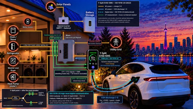
How to read the colours. Solid orange lines show alternating-current power flowing toward the household loads and, during charging, toward the vehicle (+I). The solid blue line shows power flowing from the vehicle back to the house during vehicle-to-home discharge (−I). The dashed cyan line is the ISO 15118-20 digital link between the vehicle and the charging equipment. The dashed green lines carry the current-sensor measurements to the controller; they stay inside the house and need no Internet connection.
Step 1 — Where the supply splits. Utility power enters through the main breaker. Immediately downstream, at the point marked “Y”, the supply divides into two branches: the dwelling branch, which feeds the main electrical panel and every household load, and the EV branch, which feeds the charging equipment. Because each branch is measured separately, the controller always knows how much current the house is drawing and how much the vehicle is drawing.
Step 2 — What the sensors measure. Current transformers CT1 and CT2 measure the two line conductors (L1 and L2) of the dwelling branch. Because the hybrid inverter, the solar panels and the stationary battery are connected through the main panel, these sensors see the panel’s net demand: household consumption minus any energy supplied locally by the photovoltaic system or the battery. CT3 measures the current actually flowing in the EV branch, in either direction. This third measurement lets the controller verify that the vehicle respects the limit it has been given, which is called a closed-loop check.
Role of the solar panels and the battery. The hybrid inverter combines a solar charge controller with maximum power point tracking (MPPT), which extracts as much power as possible from the panels, and a battery interface. When the sun is shining or the battery is discharging, part of the household demand is supplied locally, the net demand measured by CT1 and CT2 falls, and more capacity becomes available for the vehicle. The figure therefore shows how local generation and storage can be used to charge the vehicle without increasing the demand on the utility service.
Step 3 — How the charging limit is calculated. The energy management system subtracts the measured dwelling demand from the capacity allowed for the electrical service and offers the remainder to the vehicle. In the example shown, the vehicle charges at 32 A; at 240 V this corresponds to 32 A × 240 V ≈ 7.7 kW. If the oven, the dryer and the heat pump start at the same time, the available margin shrinks and the controller lowers the charging limit; when those loads stop, the limit is restored. This is the type of electric vehicle energy management system addressed by Rule 8-500 of the Canadian Electrical Code.
A simplified numerical example. Suppose, for illustration only, that the controller is configured to keep the total service current at or below 80 A. If the house draws 48 A, 32 A remain and the vehicle may charge at 32 A, as in the figure. If the dryer then adds 24 A, the house draws 72 A and the charging limit falls to 8 A. If further loads push the house above 74 A, less than 6 A remains, which is below the minimum current that the Control Pilot signal can advertise, so charging is paused until capacity returns. Real installations must be configured according to the applicable electrical code and the equipment ratings.
Step 4 — How the limit reaches the vehicle. The figure shows two communication paths. With a vehicle that supports ISO 15118-20, the charging equipment (acting as the SECC) and the vehicle (acting as the EVCC) exchange digital messages secured with TLS 1.3. In bidirectional operation, the charging equipment sends a target active power whose sign gives the direction of energy flow: positive values for charging and negative values for discharging [6]. The figure expresses these targets as equivalent currents (+32 A and −20 A). With any other vehicle, the charging equipment falls back to the Control Pilot PWM signal of SAE J1772 and IEC 61851-1, whose duty cycle advertises the maximum permitted charging current. This fallback can only limit charging; it cannot ask the vehicle to discharge.
Step 5 — Energy flowing back to the house. The blue path shows vehicle-to-home (V2H) operation: the vehicle exports energy (−20 A in the example) through the charging equipment and the main panel to the household loads, for instance to reduce a demand peak. This requires a vehicle and charging equipment that both support bidirectional power transfer, together with protection and interconnection arrangements accepted by the local utility and the electrical inspection authority. To keep supplying the house during a grid outage, the installation must also be isolated from the utility network, which is the role of the transfer switch shown in the figure. Without this isolation, energy could flow back into the utility lines and endanger the workers repairing them.
What the figure teaches. Three principles of this article appear together in Figure 1. First, load management is performed locally, from measurements taken at the premises, without depending on the Internet; the cloud link is optional and used only for telemetry. Second, communication and power transfer are separate functions: the same digital link can request charging or discharging, but discharging happens only if the vehicle and the power hardware allow it. Third, the household electrical service remains the limiting resource, whether the vehicle is charging, discharging or idle.
10. Conclusion: From Charging Equipment to Intelligent Energy Infrastructure
The history of residential EV charging extends from the earliest rechargeable electric automobiles to modern conductive and wireless charging systems.
The technological progression can be understood through four complementary developments:
- Standardized conductive charging interfaces.
- Adaptive local electrical energy management.
- Advanced digital and bidirectional communication.
- Stationary wireless power transfer and its potential future extensions.
- These technologies perform different functions and should not be confused.
- Physical connectors establish conductive electrical connections.
- Control Pilot PWM communicates basic charging states and permissible AC charging current.
- Local energy management coordinates charging demand with available electrical capacity.
- ISO 15118-20 enables advanced digital and bidirectional information exchange.
- Wireless power transfer replaces the conductive vehicle connection with a controlled magnetic energy-transfer interface.
- Bidirectional electrical power transfer is a separate capability requiring compatible power hardware and protection.
The residential EVSE of the near future may become much more than a device for delivering electrical energy to a vehicle. It may become an intelligent, locally managed component of the home’s electrical infrastructure, integrating conductive or wireless charging with increasingly sophisticated energy-management and digital communication capabilities.
Editorial note: This article distinguishes published technical requirements, manufacturer-reported product characteristics, and potential future developments. It does not claim that emerging technologies are universally available, that all EVs support bidirectional power transfer, or that every charging installation can be upgraded without additional engineering and regulatory assessment.
Note on the use of artificial intelligence: The author, a retired engineer working independently, used Claude, an AI assistant developed by Anthropic, for editing, drafting assistance and verification of references. The ideas, technical choices and conclusions are the author’s. This work is voluntary and non-profit. It is dedicated to the public domain under CC0 1.0 Universal.
Disclaimer: This article is for general educational purposes only. It is not engineering advice for any specific installation. Electrical work must comply with the applicable electrical code and be designed and approved by qualified persons.