How to Use the Fluke T6 Electrical Testers with FieldSense Technology

September 28, 2017
This is the second of a two-part article on Fluke’s new TC electrical tester. Part 1 explored features in benefits. Here in Part 2: putting Fluke T6 to work.
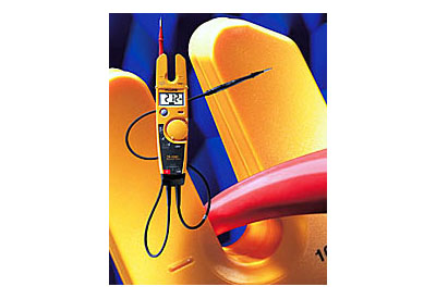
Anyone who uses electrical testers to capture measurements such as voltage and current knows that the process is traditionally time-consuming and carries the potential for risk. The Fluke T6 electrical tester with FieldSense Technology provides a faster and safer method for taking electrical readings on distribution panels and junction boxes, among other applications. This tool senses an electrical field in the open fork, allowing you to take the measurement with ease.
Typically, electricians encounter junction boxes crowded with wires, so finding the right connection point poses a challenge. T6 electrical testers go beyond simple detection. They actually measure AC voltage, current and frequency without test leads. With the use of the provided test leads, the tools are also able to measure AC/DC voltage, resistance and continuity.
The FieldSense technology measures the voltage through the cable’s insulation, reducing user hazard to exposed metallic conductors and reducing the likelihood for errors or accidentally contacting the wrong conductors. The technology injects a known signal to accurately derive the unknown AC voltage. This allows for an actual AC voltage measurement, versus simply sensing a magnetic field found in traditional non-contact voltage detectors.
Taking stable readings
The optimal position for a hot or neutral conductor when taking FieldSense measurements is centred at the bottom of the open fork. When positioning the fork, with one hand, simply slide the open fork over the conductor. For the T6-1000, the LCD display simultaneously shows the voltage and current measurements while the frequency can be manually selected with the press of a button. There’s no need to reconfigure the tool or search for metallic test points.
The display screen will turn green to indicate that FieldSense has a reliable electrical signal. The triangle-shaped voltage indicator light, marked with the lightning bolt icon, turns red if the voltage present is greater than 30 V.
Be aware that the reading may not be as accurate when the user is wearing insulated gloves, highly insulated boots or standing on an insulated ladder. These scenarios will require an external grounded lead to be connected in order to confirm a reliable reading. This is accomplished by simply touching the attached black lead to a grounded conductor, such as a conduit or a junction box.
Measuring AC voltage and AC current
Follow these four easy steps:
- Turn the dial knob to the second position, or “FieldSense” function. The tester measures and simultaneously displays both AC voltage and AC amps on the T6-1000 while the T6-600 will default to AC amps and must be toggled to AC voltage using the yellow toggle button.
- When using the touch pad to complete the ground, insert the black test probe into the storage dock on the back of the unit. If using insulated gloves, standing on an insulated ladder or otherwise insulated from ground, place the black test lead on a ground conductor or attach it to ground with an alligator clip.
- View the reading, making note of the units of measurement.
- Press the HOLD button to momentarily freeze the reading for a quick snapshot of the screen readout.
Remember, the attached test leads must be used when measuring AC/dc voltage through the traditional metallic contact method and when making phase to phase voltage measurements. Touch the probe tips to the circuit across the load or power source in parallel to the circuit.
The T6-600 is rated 600 V CAT III and the T6-1000 is dual rated 1000 V CAT III/600 V CAT IV.
Measuring resistance and continuity
The T6-1000 measures resistance 1Ω to 100 kΩ, while the T6-600 measures 1Ω to 2000 Ω. To take a measurement:
- Turn off power in the circuit to be tested.
- Turn the selector to Ω.
- Touch the probe tips across the designated component or portion of the circuit.
- View the reading.
- If the reading is less than 40 ohms, you will obtain an audible continuity alert.
Non-operating circuitry
With an energized circuit not under load, you can measure the hot leg of an AC circuit. T6 electrical testers help you troubleshoot, as they empower you to find out which wires are hot, even while the circuit — whether for a light, motor, or lamp — is non-operational. This gives electricians the ability to test wires with voltage potential and troubleshoot where the circuit is open. 3 Fluke Corporation How to use Fluke T6 electrical testers to take accurate measurements
Staying protected
Notwithstanding the T6 electrical testers’ improvements to safely taking electrical measurements, workers should still wear appropriate personal protective equipment (PPE). This means electricians should still wear arc-rated clothing and protective equipment including gloves, safety glasses or goggles, hearing protection and leather footwear. In lower voltage areas, measurements can be taken wearing minimal PPE, including gloves and protective eyewear. However, measuring without test leads does not mean you can skip wearing the required PPE.
Find out more: www.fluke.com/t6
Read Part 1 here: http://www.electricalindustry.ca/latest-news/3485-troubleshoot-electrical-systems-safer-and-faster-with-new-tester-part-1


![Guide to the Canadian Electrical Code, Part 1[i], 26th Edition– A Road Map: Section 56](https://electricalindustry.ca/wp-content/uploads/2022/11/Guide-CE-Code-2-768x432.png)


![Guide to the Canadian Electrical Code, Part 1[i], 26th Edition– A Road Map: Section 56](https://electricalindustry.ca/wp-content/uploads/2022/11/Guide-CE-Code-2.png)


