Advanced Charging Solutions for Next-Gen Commercial EVs
November 24, 2022
Three scenarios with dedicated power electronic solutions
As the electrification of heavy-duty or commercial vehicles gains more acceptance, charging larger batteries than the ones in electric passenger cars increases in importance. Because time is money, especially in logistics, the preferred options are increasing charging power or assigning idle times for charging. These preferences result in three different charging scenarios.
Scenario 1: Depot-Charging and Fleet Operation
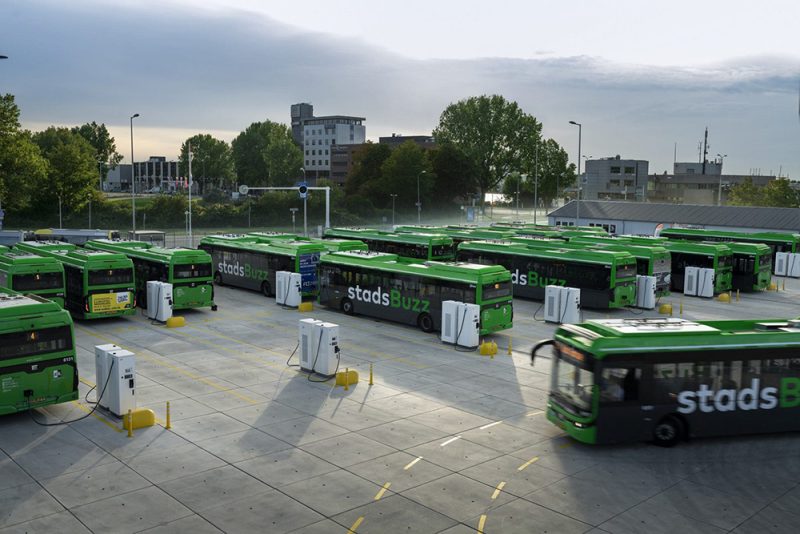
Modern battery technologies and cutting-edge power semiconductor solutions allow the design of highly efficient infrastructure. The image above depicts contemporary depot charging for bus fleets.
Depot charging is the best option for local fleet operations, particularly for buses and delivery vehicles. These are operated on relatively fixed routes and are idle during night-time hours.
This form of charging comes with a reduced demand for charging power and with further energy management options. Including stationary batteries, decoupling the time of charging buses from times of having excess energy also becomes an option.
Today’s common battery-electric buses feature battery capacities ranging from 250 to 500 kWh, which enables them to operate one shift without charging. Individual depot chargers only need to recharge one vehicle overnight, and even when recharging 80 percent of 500 kWh in 6 hours, 70 kW is sufficient. Of course, this is multiplied by the number of vehicles that must be simultaneously charged for the whole depot.
A typical charger schematic includes an input stage that can adapt the DC link voltage, an output rectifier, and a galvanic isolation stage in-between, as depicted in Figure 2.
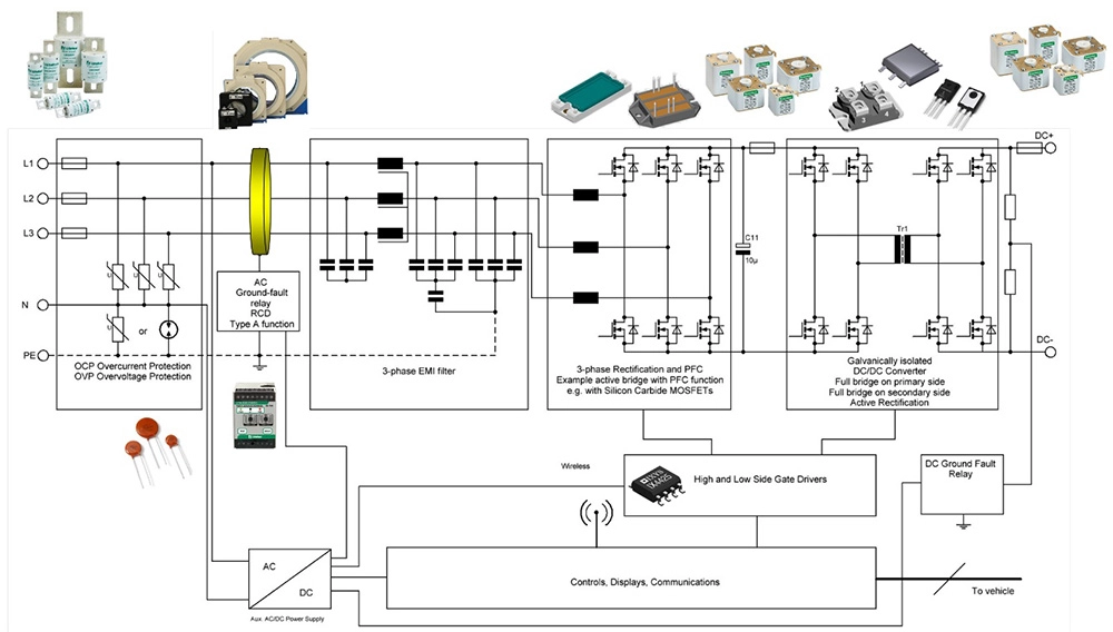
Typically, chargers are built in a modular approach from subsystems that can be stacked to increase the output power. Most standard designs feature 15-60 kW per subsystem, and the choice of components varies with the power output requirement and cooling preferences. While units with forced-air-cooling ranging from 10 to 15kW are widely built with discrete devices, higher power units use liquid cooling and are mainly constructed from multiple power modules.
Paralleling units is another option to increase output power while also building functional system redundancy. Doing so enables system operation at lower power in case of failure in a single module instead of losing the complete system.
Depot-charging also opens the door for use as secondary grid services. Stationary energy storage helps reduce the grid’s load and, during high energy demand, even supports the grid. Scheduled charging and load balancing also become an option. Charging times can align with excess energy periods, potentially resulting in lower or even negative energy prices at night.
Vehicle fleets with a fixed schedule do not need to be fully charged simultaneously. Sharing the energy between vehicles is also possible, and those not scheduled to be in service can contribute their stored energy. Holistically, depots as larger industrial areas could also become solar power stations.
Scenario 2: Opportunity Charging
Fleet vehicles operating along predefined routes open the option to extend the driving range by adding smaller amounts of energy more frequently. Called opportunity charging, this works best if it takes place in a fully automated manner.
There are two recommended solutions for opportunity charging.
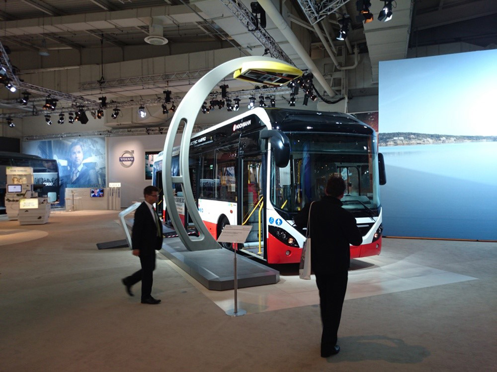
Mechanical systems, known as pantographs, allow large electric contacts to move over larger distances and safely contact their counterparts. A proven reliable technology, pantographs are widely used in tramways and railway applications. Pantographs are separated into top-down and bottom-up systems depending on the mounting position. The bottom-up approaches are mounted on the vehicle and contact the station. Top-down mechanics are a part of the station and are lowered down to the vehicle. Figure 3 shows how to set up charging by pantograph.
Construction of the infrastructure remains restricted to the roadside. Thus, such an installation can be built to upgrade existing stations where a suitable power supply is available locally. Since this is rarely the case, buffering the station by battery storage is a widely accepted solution to separate the high-power charging of the vehicle from recharging the stationary batteries.
It is common to apply power levels of 125-250 kW.
Before starting the charging process, the charging voltage and current are aligned between the station and the vehicle’s battery management systems. Because of the high power involved, charging via pantograph is always DC-charging with direct access to the vehicle’s battery.
For future installations, pantographs are the recommended solution, especially for autonomous vehicles, as it involves no plug or wire that needs precise handling. The systems can easily handle vehicles of different heights and can be constructed to tolerate misplacements between station and vehicle.
Also popular for mobile devices like smartphones, consider upgrading Wireless Power Transfer (WPT) in power to suit the needs of large-scale energy transfer. SAE J2594 describes wireless power transfer for vehicle-scale systems in detail. Wireless charging systems inherently have two independent parts that exchange energy via magnetic flux. To avoid sacrificing too much transfer efficiency, SAE J2594 sets a target for them to reach at least 80 percent transfer efficiency. Series-compensated resonant circuits, operated in a frequency range of 80-140 kHz, as illustrated in Figure 4, can be used to fulfill this requirement.
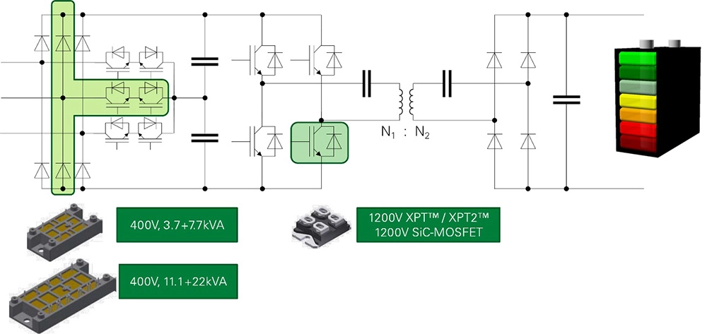
Many input rectifier topologies are worth considering, including static diode rectifiers as a cost-optimized solution or thyristor-based versions. The Vienna Rectifier is a common solution due to superior EMI behavior, the reduced effort necessary for filtering, and the adjustable DC link voltage. With the high switching frequency of 80 to 140 kHz to drive the sending coil, as required by the standard, using IGBTs with low switching losses or SiC-MOSFETs for the DC-DC conversion stage can be considered.
Inductive chargers have to be installed where vehicles can run over them. In contrast to pantographs, this severely impacts the infrastructure, especially in public traffic. Therefore, inductive charging is a suitable solution, primarily for semi-public areas. For example, airport baggage trolleys can benefit from wireless power transfer as the power levels, energies involved, and topographic conditions suit the application’s requirements.
Scenario 3: Individual Long-Haul Operation
Traveling on random routes, as long-haul logistics demands, requires individual high-power charging similar to today’s gas stations. This high-power charging needs to become part of the existing infrastructure to allow for the seamless integration of electric trucks into the mobility sector.
With a DC voltage up to 1500 V and a maximum charging current up to 3000 A, charging at rates exceeding 2 MW becomes possible.
At 2 MW charging, 500 kWh to go another 300 km can be delivered in about 15 minutes which is well covered by the breaks a driver must take to comply with legal requirements. However, urban low-voltage 3-phase grids up to 400 V would not support this power level.
In this scenario, locally supplied power from the medium-voltage regime must be considered a prerequisite. Though buffering by stationary batteries is a potential option, the capacity for the storage would become comparatively large.
Having to work from a medium voltage transformer leads to a promising option for chargers in the megawatt regime. Instead of scaling up the structure used to charge passenger cars, following the well-established scheme used in electrolysis comes to mind. Figure 5 depicts the correlating high-power setup.
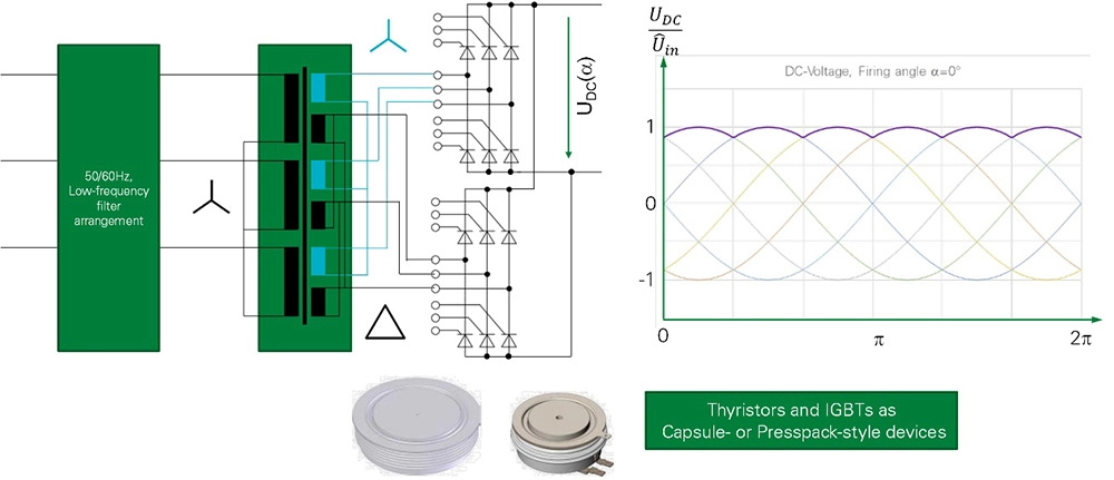
This approach only features a single stage of energy conversion and displacing the stage of galvanic isolation from smaller individual converters to the medium-voltage transformer enhances the efficiency of the power conversion stage to exceed 99 percent. At the same time, it minimizes the number of resources per kW installed, and an assembly built from presspack components reduces space demands.
When tapping into the megawatt regime, thyristor-based solutions combine outstanding efficiency with capsule-type devices’ unprecedented lifetime and reliability.
Such infrastructure systems demand a high number of operating cycles and pose extraordinary expectations towards time-in-service. Designers need to consider both during the early stages of design. Though technology and topology may appear outdated, the higher efficiency, lower cost, and reduced space requirements make it the obvious choice. This approach will be critically important when the future autonomous commercial vehicles demand even higher power ratings to reduce charging times further as no recreational break for a driver is required.
To learn more, download the white paper, Reducing Emissions Through Electrification, courtesy of Littelfuse, Inc.