A Road Map to the CE Code, Part 1 – Installment 4
William (Bill) Burr
The CE Code is a comprehensive document. Sometimes it can seem daunting to quickly find the information you need. This series of articles provides a guide to help users find their way through this critical document. In this article: Section 6. The article is not intended to replace the notes in Appendix B or the explanations of individual requirements contained in the CEC Handbook, but will hopefully provide some help in navigating the code.
Section 6 – Services and service equipment
This section of the code outlines the rules applicable to the electrical installation of service equipment, including the consumer’s service and the supply service. As per the definitions in Section 0, a consumer’s service includes all that portion of the consumer’s installation from the service box or equivalent, up to the point where the supply authority or local utility makes connection.
Note that “supply authority” can include public utilities as well as private electrical power networks that are deemed to be supply authorities by the regulatory authority having jurisdiction. Also, according to the scope outlined in Section 0,equipment and work employed by the supply authority, in its function as a utility, are not covered by this code.
However, this section does have rules only for the attachment point of the supply service. The rest is deemed to be outside the scope of the code since it is installed by the utility.
As noted above, this section deals with all electrical services. However, services and service equipment over 750 volts may be modified by rules in Section 36 – High-voltage installations.We will discuss these modifications when we get to Section 36, but if you are intending to install a high-voltage service be aware there may be rating, capacity and overcurrent protection modifications for high-voltage service equipment rules.
Other Section 0 definitions that relate to Section 6 are a supply service — the supply conductors as mentioned above, and a service box — an assembly containing an enclosure that can be locked or sealed and containing a switch or breaker that can be opened when the box is closed.There is also one special terminology definition applicable to this section: a transformer rated meter mounting device, a meter mounting device with current transformers that may have test switches mounted in the same enclosure.
The General part of Section 6 deals with the number, arrangement and location of electrical services.
Normally, according to Rule 6-102, only one service is run to a building, however, more than one supply service could be permitted to run to any building provided that each supply service is supplying:
• fire pumps, in acccordance with Section 32
• an industrial establishment, or
• completely self contained row type occupancies, with separate entrances to ground level
The service boxes for such supply services associated with multiple supply services must be grouped, where practicable.Where this is not possible, a permanent diagram must be affixed beside each supply service box indicating where the other service boxes are located. In any case the Appendix B note to this section advises that it is prudent to consult with the supply authority on the number and location of supply services.
Rule 6-104 further provides for a maximum of four consumer’s services of the same voltage and characteristics (normally number of phases) run to any one supply service. The following Rules 6-104 to 6-110 discuss rules regarding service supply from more than one system, from an electric railway, and requirements for a 3-wire system where more than two 120 volt circuits are installed.Rules 6-112 to 6-116 outline the requirement for support, clearance, and termination of consumer’s service conductors and location of a consumer’s service head. The Appendix B notes for this section are very helpful in designing and installing a consumer’s service.
The Control and Protective Equipment part of this section specifies how services are controlled, as well as measures for the protection of persons and property.Rules6-200 to 6-204 delineate the need for and for the arrangement of service boxes. Rules 6-206 to 6-214 discuss the location of consumer’s service equipment and conductors, the use of oil switches and oil circuit breakers as service switches, wiring space in enclosures, and marking of service switches. Again, note that Appendix B suggests that the local regulatory authority be consulted regarding the locking of service boxes in the ‘on’ position and regarding the location of service boxes and meter mounting devices, as the supply authority requires access to this service equipment.
The Wiring Methods part of Section 6 has guidelines for the selection, minimum size and installation of consumer’s service conductors. Rules6-300 to 6-304 address the installation of underground consumer’s service conductors,the installation of overhead consumer’s service conductors and the use of mineral insulated and aluminum sheathed cables. Rule6-306specifies that consumer’s service raceways must contain only consumer’s service conductors, be protected from mechanical damage, and have a minimal cross section size of 21mm. Rules 6-308 to 6-312 treat the use of bare neutral conductors, the use of joints in neutral conductors and the draining of condensation in consumer’s service raceways.
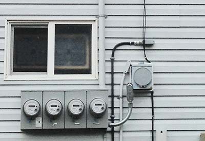
The Metering Equipment part gives us the guidelines for selection, arrangement and installation of meters and metering equipment. Metering equipment includes current and potential transformers and associated measuring equipment. Rules 6-402 to 6-410 outline the location and method of installing meter loops, selection and installation of instrument transformer enclosures, disconnecting means for meters,location of meters and the space required for meters.Finally, Rule 6-412 has specifications for metering impedence grounded systems.
These are the specific rules that apply to all services. However, the rules of the other general sections also may apply to services and service equipment selection and installation.
In the next installment:Section 8 – Circuit loading and demand factors.
Read the rest of the instalments in the series:
Part 1: Guide to the CE Code, Part I – A Roadmap (Installment 1 in a Series)
Part 2: A Road Map to the CE Code, Part I – Installment 2
Part 3: Guide to the Canadian Electrical Code, Part I – Installment 3
Part 4: A Road Map to the CE Code, Part 1 – Installment 4
Part 5: Guide to the Canadian Electrical Code, Part I — Installment 5
Part 6: Guide to the Canadian Electrical Code, Part I — Installment 6
Part 7: Guide to the Canadian Electrical Code, Part I — Installment 7
Part 8: Guide to the Canadian Electrical Code, Part I — Installment 8
Part 9: Guide to the Canadian Electrical Code, Part I — Installment 9
Part 10: Guide to the Canadian Electrical Code, Part 1 – Installment 10
Part 11: Guide to the Canadian Electrical Code, Part 1 – Installment 11
William (Bill) Burr is the former Chair of the Canadian Advisory Council on Electrical Safety (CACES), former Director of Electrical and Elevator Safety for the Province of BC, and former Director of Electrical and Gas Standards Development and former Director of Conformity Assessment at CSA Group. Bill can be reached at Burr and Associates Consulting billburr@gmail.com.


