DC Resistance Unbalance Testing: Easy, Low-Cost Insurance for Your PoE Systems, Part 1
August 10, 2016
Originally ratified by IEEE in 1999 and 2003 respectively, gigabit Ethernet (1000BASE-T) and power over Ethernet (PoE) are two network technologies that today are considered the norm. With both technologies supported by an estimated 85% of the installed cabling base, they have proliferated in tandem over the past decade to the point where the many enterprise entities are deploying, or planning to deploy, gigabit Ethernet in the horizontal LAN environment and more PoE devices than ever before.
While 10/100BASE-T (i.e., 10 and 100 Mbps) applications required only two cable pairs for transmission, leaving two spare pairs of a four-pair twisted cable available for PoE, gigabit Ethernet requires all four cable pairs for bidirectional transmission. In this scenario, PoE is delivered over pairs that are simultaneously transmitting data.
Often referred to as phantom power and accomplished by applying a common-mode voltage between two pairs in a four-pair Ethernet cable, PoE is intended to not interfere with data transmission. However, DC resistance unbalance in a PoE connection has the potential to cause significant problems. While not required in TIA or IEC performance field testing, resistance unbalance is specified in the IEEE’s PoE standards and making DC resistance unbalance testing a field test requirement will go a long way in ensuring that devices get the power and data they need. As we move towards a new PoE standard in the future, to be known as IEEE 802.3bt and capable of up to 100W, that two pair PoE delivery will move to a four pair PoE delivery. Not only will DC resistance unbalance within a pair be a potential cause of problems, but we will also need to consider pair to pair DC parallel resistance unbalance as another source of potential problems.
Understanding PoE and DC resistance unbalance
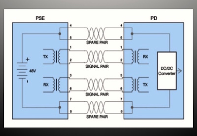
The IEEE 802.3af standard for PoE was developed to provide remote low-voltage power to devices over twisted-pair data cabling. Power is injected by power sourcing equipment (PSE), which is typically a PoE-enabled switch or a mid-span power device. The power can be used by a wide range of powered devices (PDs) at the other end, including VoIP phones; wireless access points (WAPs), wall clocks, sensors, cameras, access control panels and more.
The original IEEE 802.3af standard allows for delivering a maximum of 15.4 W (13 W available) of power over two pairs, while the current IEEE 802.3at PoE Plus standard increases the allowed maximum power to 30 W (25.5 W available). The new proposed IEEE 802.3bt PoE Plus Plus standard is designed to provide 100W of power when ratified. PoE Plus was developed in response to more power-hungry devices such as higher power WAPs, pan-tilt-zoom cameras, LED display boards and more. In fact, the latest 802.11ac standard for gigabit Wi-Fi has higher power requirements due to more sophisticated signal processing and a higher frame rate that requires PoE Plus. PoE Plus Plus is being developed to provide power to even more power hungry devices such as multiple radio WAPs, CCTV cameras that also include PTZ and heaters, LED data centre lighting, with many more uses being envisaged.
The IEEE 802.3af and 802.3at standards specify two methods for PSE to provide power using two pairs of a four-pair data cable — Alternative A and B. In Alternative B, power is delivered over spare pairs using Pairs 1 and 4. This is compatible with data signals that only use two pairs (Pairs 2 and 3), including 10/100BASE-T applications. In Alternative A, the power is delivered simultaneously with data over Pairs 2 and 3, which is compatible with both two-pair and four-pair applications, including 10/100BASE-T and 1000BASE-T.
In Alternative A, power is transmitted over the data pairs by applying a common-mode voltage. Power is received and returned using the centre tap of a PD’s transformer, which splits the current between each conductor of the pair. When the resistance of each wire in the pair is equal, the DC resistance unbalance (the difference in resistance between two conductors) is at zero, current is split evenly, and common-mode current is achieved.

With IEEE 802.3bt, we move to a 4 pair based system to deliver the required power. We still have our PSE and PD devices, with the current flow now shared among the four pairs.

While devices can tolerate some DC resistance unbalance, too much unbalance causes the potential for saturation of the transformer. This can ultimately distort the waveform of Ethernet data signals, causing bit errors, retransmits and even non-functioning data links. With a four pair PoE system some DC resistance unbalance between the pairs can be tolerated, but if it is excessive, PoE will stop functioning.
What causes DC resistance unbalance?
DC resistance unbalance within a pair and between pairs can occur in a PoE data link for a variety of reasons. While problems with transformers such as an offset centre tap can occur at both PSE and end devices, DC resistance unbalance is more often caused by poor workmanship, inconsistent terminations and subpar cable quality.
Poor installation practices have long been at the crux of network performance problems. Practices such as ensuring minimum bend radius and maintaining pair twist as close to the point of termination as possible are key to meeting performance parameters, especially in higher frequency applications like 1000BASE-T and 10GBASE-T. While PoE relies more on the DC resistance of a specific length of cable rather than high-frequency transmission characteristics, there are some installation practices that matter.
Consistency in individual conductor terminations is important to preventing DC resistance unbalance. Punching down the individual conductors to the proper IDC tower of a network jack displaces the conductor’s insulation to expose the copper and make the connection.
Ensuring proper and consistent seating during this practice isn’t always easy. A certain amount of force is required to seat the conductors, and inexperience, hand fatigue and larger conductor gauge sizes can all impact the ability to maintain consistency. When two conductors of a pair carrying PoE are terminated inconsistently, DC resistance unbalance can occur. Using the correct termination tool can help increase termination consistency and avoid DC resistance unbalance in PoE systems (see sidebar on termination tools).
Conscientious terminations must also be coupled with precision manufacturing processes as the overall quality of the cable and connectivity can also impact DC resistance unbalance. Manufacturing quality UTP cable requires careful selection of copper conductors and the use of stringent controls to maintain the proper physical geometry of the cable. When a poor quality cable exhibits variations in the diameter, concentricity (roundness), contour and smoothness of the copper conductors, there is a higher risk for DC resistance unbalance in PoE systems.
One of the growing concerns in the industry today is the significant amount of cables containing copper coated aluminum (CCA), copper coated steel and other non-standard conductors masquerading as Category 5e or even Category 6 cables. While these cables can be appealing to those looking for inexpensive networking solutions, CCA cables are not compliant with industry standards and do not support PoE applications due to their increased DC resistance, which can be 55% greater than for a solid copper cable of the same diameter. The greater resistance results in greater heating of the cable and lower voltage available at the powered device.
Unfortunately, testing for DC resistance is not always enough to determine support for PoE as some CCA cables will pass DC loop resistance testing for shorter links. However, regardless of link length, CCA cable will typically feature DC resistance unbalance on pairs due to lack of consistency across conductors (see sidebar on DC loop resistance vs. DC resistance unbalance). It should also be noted that both the ANSI/TIA and ISO/IEC standards require twisted pair data cable to be 100% copper.
Read Part 2: testing for DC resistance unbalance within a pair and between pairs.
This article was originally published online by Fluke: http://www.flukenetworks.com/content/white-paper-dc-resistance-unbalance-testing-easy-low-cost-insurance-your-poe-systems.