Guide to the Canadian Electrical Code, Part 1 , 25th Edition – A Road Map: Section 80
February 6, 2023
By William (Bill) Burr
The Code is a comprehensive document. Sometimes it can seem quite daunting to find the information you need quickly. This series of articles provides a guide to help users find their way through this critical document. This is not intended to replace the notes in Appendix B or the explanations of individual requirements contained in the CEC Handbook** but will hopefully provide some help in navigating the Code.
Section 80 — Cathodic Protection – (The 25th Edition of the CE-C, Part I, (C22.1-21) * is available from CSA Group. This discussion of Section 80 is based on this edition).

Rule 80-000 notes that this is a supplementary or amendatory section of the code and applies only to the installation of impressed current cathodic protection systems. Appendix B and the CEC Handbook have additional information and descriptions of Cathodic Protection. This Section considers that the wiring methods used in installing such systems are sometimes inconsistent with the requirements of other Sections of the Code.
Rule 80-002 mandates the wiring methods for DC wiring and includes:
- conformance to Section 12requirements, except when buried below ground of not less than 450mm or 200mm when in a raceway or with mechanical protection, and
- conformance to Section 18 and Section 20whenin hazardous areas.
Where DC wiring is installed underground below a Section 20 (Annex J20) Class I hazardous area, it may be buried to a depth not less than 450 mm or 200mm in threaded rigid conduit and sealed in accordance with Rules 18-104 or 18-154, where it emerges from the ground.
Rule 80-004 requires that DC cathodic protection wiring be a minimum No. 12 AWG, except for instrumentation and reference electrode leads, and be selected in accordance with Rule 12-102 3) regarding location and conditions of use.
Rule 80-006 specifies that splices, taps and connections made in conductors underground or exposed to the weather must be:
- made by welding, by a positive compression tool, by crimping and soldering, or by means of a copper, bronze, or brass cable connector.
- sealed against moisture by taping or other methods as effective as the original insulation.
- connected to piping by thermit welding or by a clamp of the same material as the piping or anodic to it;
- connected to a tank or other structure with a welded stud, thermit welding or other permanent means; and
- sealed against moisture by applying a material resistant to any corrosive environment.
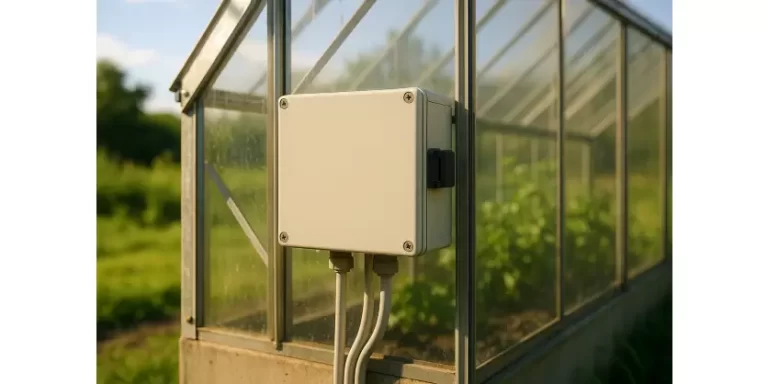
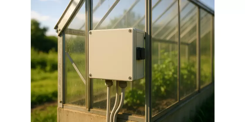
Rule 80-008 requires that the cathodic protection system rectifier be provided with a dedicated circuit in accordance with the requirements of Section 12.
Rule 80-010 outlines that each rectifier unit of a cathodic protection system must have a separate disconnecting means installed that is:
- readily accessible,
- within sight of, and
- within 15 m of the unit, or
- integral to the rectifier and equipped with:
- barriers or other suitable means to protect service personnel from live parts on the line side, and
- rendered inaccessible to unauthorized persons by a lockable cover, and
- labelled in a conspicuous, legible, and permanent manner identifying it as the disconnecting means for a cathodic protection system.
Rule 80-012 requires that where the available operating voltage is more than 50V:
- the voltage difference between exposed points of the protected system, or
- any point in the vicinity of the anodes, and any point 1m away on the earth’s surface, not exceed 10V.
Rule 80-014 requires that the following warning signs and drawings be provided:
- A marking warning on tanks, pipes and structures that the cathodic protection system is not to be disconnected unless the power source is turned off.
- A sign, in a conspicuous location adjacent to the disconnecting means of electrical apparatus connected to the cathodically protected structures, advising that the cathodic protection be turned off and a temporary cathodic protection bypass conductor, appropriately sized for maximum available current, be installed before equipment or piping is replaced or modified.
- In a non-hazardous location, a sign advising that the use of a temporary cathodic protection bypass conductor, appropriately sized for maximum available current, may be used as an alternative to turning off the cathodic protection when replacing or modifying the protected equipment.
- A drawing, placed inside or near the rectifier cabinet, showing the location, polarity and anodes of underground cathodic protection wiring.
- A notice, placed in a conspicuous location adjacent to the entranceway of a storage or process container, advising that the cathodic protection system must be turned off before entering the container.
In the next installment, we will discuss Section 84 – Interconnection of Electric Power Production Sources.
Source: CSA C22.1:21, Canadian Electrical Code, Part 1 – Safety Standard for Electrical Installations. © 2021 Canadian Standards Association. Please visit store.csagroup.org. With the permission of CSA Group, material is reproduced from CSA Group standard CSA C22.1:21, Canadian Electrical Code, Part 1 – Safety Standard for Electrical Installations. This material is not the complete and official position of CSA Group on the referenced subject, which is represented solely by the Standard in its entirety. While use of the material has been authorized, CSA Group is not responsible for the manner in which the data are presented, nor for any representations and interpretations. No further reproduction is permitted. For more information or to purchase standard(s) from CSA Group, please visit store.csagroup.org or call 1-800-463-6727. [1]
William (Bill) Burr is an associate member of the Canadian Electrical Code, Part 1, Technical Committee and formerly Chair of the Canadian Advisory Council on Electrical Safety (CACES), Chief Electrical and Elevator Inspector for the Province of BC & the Northwest Territories, Director of Electrical and Gas Standards Development and Director of Conformity Assessment at CSA Group. Bill can be reached at Burr and Associates Consulting billburr@gmail.com


