The Poet’s Guide to the Physics of Twisted Pair Cabling
Feb 26, 2020
I once took a class where the professor would explain concepts in two ways. First, he would dive into the mathematics behind the idea, filling the whiteboard with equations and showing how they all related to one another. He tagged this “for the engineers,” Then, he would explain the concept again, but this time, with no math at all. This he said, was “for the poets.”
So why is datacom cabling twisted, but power cabling is not? It’s all about bandwidth. Power signals are of such low frequencies that they don’t need to worry about bandwidth, but datacom cables do. A high frequency signal on a wire generates a magnetic field that can induce a signal on an adjacent wire. These induced signals are called “crosstalk,” because with old analog telephone lines, you could often hear other conversations in the background of your call resulting from these induced signals.
Imagine the Ethernet interface in your computer transmitting a signal. When a signal is sent on the transmit (Tx) line, a signal is induced on the receive (Rx) line. That’s a problem because the rules of Ethernet state that you stop talking if someone else is talking at the same time. But if every time your computer tried to talk, it would hear itself, and stop. Looks like you won’t be sending the email after all.
In reality, the induced signal is many times weaker than the original, which makes this less of a problem. However, the receive electronics need to be very sensitive. That’s because high frequency signals attenuate greatly over the length of a cable. For example, the IEEE 802.3 specification for 1000BASE-T allows a maximum of 24 dB of loss, which translates to a signal being reduced to (I’ll do the math for you poets) 6% of its original strength on its trip from the far end transmitter to your computer’s ethernet port. So the crosstalk signal does not have to be big to overwhelm that. As you move further from your computer interface, the received signal gets stronger and is less susceptible to crosstalk. That means the problem is worst nearest to the transmitter, so the key specification is called Near End Crosstalk or NEXT.
Engineers have a number of tricks up their sleeves to deal with NEXT. First, data signals are encoded onto a cable in “differential” mode — that means that every positive pulse on a conductor is matched by a corresponding negative pulse on the other conductor in the pair. That means that the wires generate equal but opposite magnetic fields that cancel each other out and should generate no crosstalk. However, if the wires simply run parallel to one another, then one wire in the pair will be closer to one of the fields, so the magnetic field will be just a little bigger for one wire than the other and you’ll get a little bit of crosstalk.
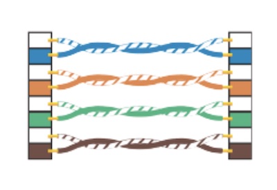
So the second trick is twisting the cable. That way, the distance between the wires varies along the length of the run, sometimes closer to the positive wire, other times closer to the negative. This tends to cancel out the effect reducing the crosstalk even more. But if the pairs are all twisted at the same rate, it’s possible that they would keep the same spacing over the entire run, resulting in increased crosstalk. That’s where the third trick comes in – the pairs are twisted at different rates so they won’t remain equally spaced to the same conductor along the run.
The different twist rates are why you’ll see different lengths for each pair when you measure the length of each with a cable tester. If you were to untwist them and stretch them out flat, the ones with more twists would be a little bit longer. Length can differ by 5% or more — the TIA limit for cabling length is based on the shortest pair.
Even though the conductors run in parallel for only a short distance in the modular (RJ-45) connector, they typically are the biggest contributor to NEXT on an installed link. And just a little too much untwisting when installing the connectors can enhance the effect enormously and lead to links failing certification.
Newer designs achieve better crosstalk performance by using spacers in the cabling, more carefully controlling twist rates, and bonding the pairs together. And new technologies such as 10GBASE-T and PoE require more than just great crosstalk performance. But crosstalk is still one of the most important parameters in terms of high performance cabling.
If you are interested in a cable tester, check out our Copper Selection Guide.
This article was first published online by Fluke Networks.