Choosing the Proper Components for Your Cable Assembly or Wire Harness, Part 2
August 17, 2017
By Brian Morissette
In this second of a two-part series, we continue discussing options to consider when designing a cable assembly or wire harness, such as the best materials to use to meet the expectations of the assembly installation, the proper termination method for the type of signal that will be transmitted over the assembly, and what safety certifications the assembly will need to comply with based on the environment. Here in Part 2: conductor twisting/cabling, shielding, outer sheaths, connectors/strain reliefs, and safety certification.
Twisting/cabling of conductors
Invented by Alexander Graham Bell in 1881, the twisting of wires is done to cancel out EMI (electromagnetic interference) from external sources. The most common noise problem is with cables used for telecommunications, where pairs in the same cable are next to each other for long distances. Because of the proximity, one pair can induce crosstalk onto an adjacent pair and this noise is additive along the length of the cable.
Twisting the pairs of a cable counters this effect due to the pairs only being near each other on the half twist. If an assembly is going to be used for communications or a data signal transmission, consider twisted pairs to eliminate any risk of noise or EMI impacting the performance of the assembly.
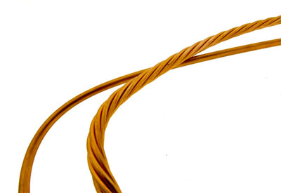
The conductors or twisted pairs are also cabled together. The cabling is a manufacturing operation where the conductors or pairs are helically wrapped together, or “cabled” together. The cabling serves several purpose: it provides for a more flexible assembly, and it also produces a round configuration that will allow for an aesthetically pleasing end assembly.

Figure: Image ot the left is a cable utilizing conductors, not twisted pairs.
Shielding
To further control both EMI/RFI, overall shields can be applied once the conductors/pairs are cabled together. There are several options for overall shields, with each having advantages and disadvantages. One of the most popular shields is a metalized foil adhered to a polyester backing, known as a foil shield. The foil shield is the lowest cost to apply, has fairly good flexibility but not good flex life, and is good at higher frequencies but is less effective at low frequencies.
Another option for an overall shield would be a braid shield. This type of shield is composed of many small diameter wires that are “braided” onto the cable core using specialized equipment known as braiders. This type of shield is more costly and more difficult to terminate than a foil shield, but offers better shielding at lower frequencies and provides for better flex life.
A different type of shield is a spiral shield where small diameter wires are wrapped around the cable core. This type of shield provides excellent flexibility with long flex life but is poor at protecting at high frequencies and is difficult to terminate.
The best protection against EMI/RFI comes from a combination of foil and braid shields. This combination provides excellent protection at all frequencies and is easy to terminate, but is usually the most costly option.

Figure: Example to the left illustrates a combination of a foil and a braid shield used to control EMI/RFI.
Outer sheath
When the cable core is finished being constructed, an outer sheath or jacket is applied. This jacket is a protective covering and is called upon to be flame retardant to meet UL and/or CSA requirements. The outer jacket can also be called upon to be physically tough to protect the cable from harsh environments, be flexible to allow movement of the assembly during both the installation and during the life cycle of the equipment it is installed on, be chemically resistant, and be semi-conductive in some applications.
The jacket can be made from many different materials, with the type of material used dependent on the environment the assembly will be installed in. PVC is the most widely used and cost effective compound currently in use. Other materials that could be used are urethane-based products that are used for severe service applications, elastomer-based products that are an acceptable substitute for rubber in many applications, fluorocarbons that offer extremely good fire resistance and physical toughness, alloy-based materials that offer properties of several different materials previously mentioned, and lastly non-halogen materials that offer low-smoke, low toxicity, and low acid generation if exposed to fire.
Connectors/strain reliefs
There are many options available for the cable assembly designer when it comes to the connectors to be used on the assembly. The type and speed of the signal being transmitted will drive the connector choice. For instance, if power is to be sent through the assembly, a crimp type connector could be chosen, or if a high speed signal is to be transmitted a solder or welded type connection will be used. The options for a connector could be limited based on the equipment the assembly will be used on. There may be a connector already chosen and installed on the equipment the assembly will have to mate to. In this situation, the connector choices will be very limited.
Another choice the cable assembly designer will need to make is whether a strain relief will be needed. The strain relief provides a transition point from the cable to the termination area and prevents a load applied to the cable from being transferred to the terminations, causing termination failure. There are options for a strain relief, such as a solid or a segmented design. The segmented design provides the greatest amount of bend relief, but is more difficult to keep clean if used in sterile environments.
Safety certification
One of the major concerns when designing a cable assembly or wire harness is location. The key factor is the region of the world where the assembly will ultimately be used, the safety certifications that the specific region regards as law, and the environmental standards that need to be met by the assembly.
Many countries have their own regulatory and safety standard agencies that enforce the examination and testing of electrical devices. For instance, in North America UL and CSA are the regulatory and safety standard agencies that set the guidelines for installations.
Beyond North America, most countries will have their own agencies that compose the installation standards for their country, with the majority of those countries using IEC (International Electrotechnical Commission), CEE (International Commission for Rules for the Approval of Electrical Equipment), or CENELEC (European Committee for Electrical Standardization) as the basis for the guidelines.
There are also environmental standards that limit or restrict the use of hazardous substances in products. The REACH and RoHS directives are two such standards limiting the use of hazardous substances. In addition to REACH and RoHS is the WEEE Directive. The WEEE Directive governs the disposal and recycling of electronic and electrical products when products are at the end of their usable life.
In addition to safety and environmental standards, assemblies may also need to meet industry standards based on specific performance criteria. Depending on the application, the cable assembly may need to meet criteria such as HDMI, SFP+, QSFP, TIA/EIA 568-C.2, or the assembly may need to be verified by an independent testing service such as ETL.
Conclusion
In conclusion, there are a number of factors to determine when designing a cable assembly or wire harness for your application. Every specification of the design needs to be addressed upfront before manufacturing can begin. Disregarding some of these important factors could hurt the performance of the final product and could also affect the price if over or under designed. If you are designing a product that requires a cable assembly, it is always a best practice to bring up all the details with your manufacturer regarding the full application to help determine what the proper cable assembly will best suite your end products needs.
Brian Morissette is Cable Assembly Product Manager Epec Engineered Technologies. This article was first published online by Epec: http://www.epectec.com/articles/choosing-the-components-for-your-cable-assembly.html